You do not have to be a fully qualified mechanic in order to install a Dobeck EFI controller. If you are at all uncomfortable about doing the installation then we do recommend going to your closest dealer and have them install the product. Most vehicle installations take less than an hour. There is really only a few parts of information to understand and you are ready to start your installation.
The following is only generic installation instructions. Browse the product section to your particular vehicle to check if advanced installation instructions are available. Some vehicles will also have installation videos in the product section. If nothing is listed for your vehicle then please contact us and we can further assist you.
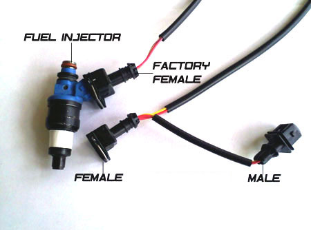
Most controller installations plug in right at the injector. These typical installations will have a male and female connector grouped together on the controller harness (refer to Figure 1). For 2 or more cylinder vehicles there will be the equivalent number of connector groups on the controller harness. Some applications install at a sub-harness location to make the installation easier. These applications will have a larger connector with usually 4 or more wires being plugged in.
Most helpful tool during the installation: OWNER'S MANUAL. Most owner's manuals will explain and sometimes illustrate where and how to access the injectors.
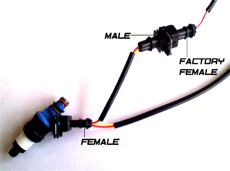
Connection Basics: The goal of the installation is to gain access to the injector signal in order to change the signal which fires the injector and fuels the vehicle. First step of the installation is to remove the necessary bolts and parts to gain access to the injectors. Once the injectors are located then the installation is the same on all vehicles. First remove the factory injector connector. Make sure not to just pull on the connection. Most connectors have a release clip which locks the connector in place and needs to be pressed in order to release the connection. Second step is to plug the similar controller harness connector back onto the injector. Final step is to plug the other controller harness connector into the stock injector connector which you originally took off (refer to Figure 2 for a completed install on 1 injector). For multiple cylinder vehicles you may have to repeat this step for all the injectors. PLEASE ONLY DISCONNECT ONE CONNECTOR AT A TIME.
Other Facts:
For multi-cylinder vehicles, it usually does not matter which controller harness connector grouping gets plugged into which injector. The most important connector has RED and YELLOW wires and is referred to as channel 1 for the controller. The importance is because the red wire signals the power wire which is how the controller powers up to operate. Some applications are cylinder specific (2008 and newer Harleys) and you may need to view the advanced installation information.
Some vehicles have primary and secondary injectors. Most commonly the controller plugs into the primary injectors only. Some applications will also plug into only 1 of the secondary injectors for the purpose of calculations into our Load Based Technology.
Figure 1 - Shows a factory connection onto an injector with an controller harness alongside.
Figure 2 - Shows a controller harness plugged into an injector creating the loop around to change the signal.
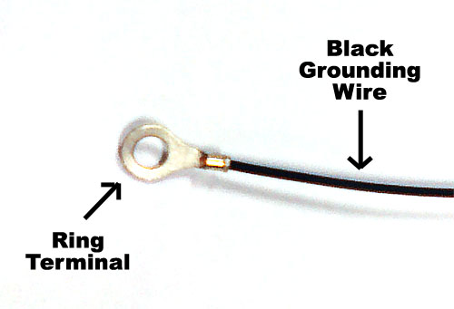
One of the largest causes of controller erratic behavior which results in tech calls is associated to improper grounding. All controllers have a BLACK wire with a ring terminal which during installation needs to be secured to a proper grounding location.
If your vehicle has a battery then attach the controller BLACK wire to the negative terminal of the battery. The ring terminal can easily be cut to allow fitment around a larger terminal post or bolt.
For vehicles without a battery then an alternative grounding location must be determined. The grounding location must be metal. Any location with a bolt into the metal frame is a good location. Be sure to make the connection secure so vibration can not cause the wire to become disconnected.
Figure 3 - Displaying the BLACK ground wire and ring terminal
Mounting the controller is about user preference. There is no exact location where the controller has to be mounted.
The controller is very small in size to allow for mounting in small places. Typical mounting locations are under the seat or in the air box. A Velcro patch is supplied with the controller to hold the controller in place while riding, but allow for the controller to be pulled out to make adjustments if necessary. Be sure to determine a location which does make the controller accessible without having to take off too many other parts.
Zip ties are also included in the packaging to help secure the harness around the frame and away from high heat sources and moving parts. Be sure to route the harness in a way where the vehicle can be freely operated without pulling on the controller connections.
A number of newer vehicles implement the use of narrowband O2 sensors to help target a desired air/fuel ratio (AFR) for the engine to operate at. For racing and performance scenerios the O2 sensors must be bypassed in order to allow for complete range of tuning. The purpose of bypassing the O2 sensors is to allow the vehicle to run in open loop mode where fuel adjustments can be made freely. When the vehicle is using the O2 sensors to make fuel trim calculations it is said to be in closed loop mode. Attempting to make fuel adjustments while the vehicle is in closed loop mode can create erractic drivability as the stock system continually tries to trim back to the desired AFR.
How to interface with the O2 sensors is different from vehicle model to vehicle model. The goal of properly bypassing the O2 sensors is to not throw an engine code and allow the fuel to be freely adjusted. Some vehicles require the O2 sensor connections to simply be disconnected. Some vehicles require an O2 bypass module to be plugged into the stock O2 connections. And still other vehicles have additional connectors on the controller harness to plug into the O2 sensors similar to installing onto the injectors. If your vehicle is equipped with O2 sensors then be sure to find out how you are suppose to interface with them. This information can be found by browsing to the particular product for your vehicle.
For emission controlled vehicles the O2 sensors can not be bypassed or disconnected in anyway. Be sure to check your state or even country laws dealing with emission regulations.